Our UFH CAD Design Process
We’ve structured our UFH CAD design process to minimise delays and site queries, while ensuring every layout is calculated and compliant.
Most projects follow a straightforward workflow:
Professional UFH Design for New Build & Retrofit Projects
Contractors often require UFH designs that are:
- in accordance with BS EN1264 and CIBSE Standards
- suitable for multiple floor areas and zones
- coordinated with site timelines
- easy for installers and screeders to follow
We support projects ranging from single plots to larger commercial floors.
A Simple, Professional UFH Design Workflow
We’ve structured our UFH CAD design process to minimise delays and site queries, while ensuring every layout is calculated and compliant.
Most projects follow a straightforward workflow:
1. Send Us Your Project Information
To begin, we typically require:
- floor plans or drawings
- project type (new build or retrofit)
- floor construction details
- required zones or control preferences
- manifold locations
- heat source
- site timescales and urgency
Clear information upfront allows us to deliver quickly.
2. Design & Output Calculations
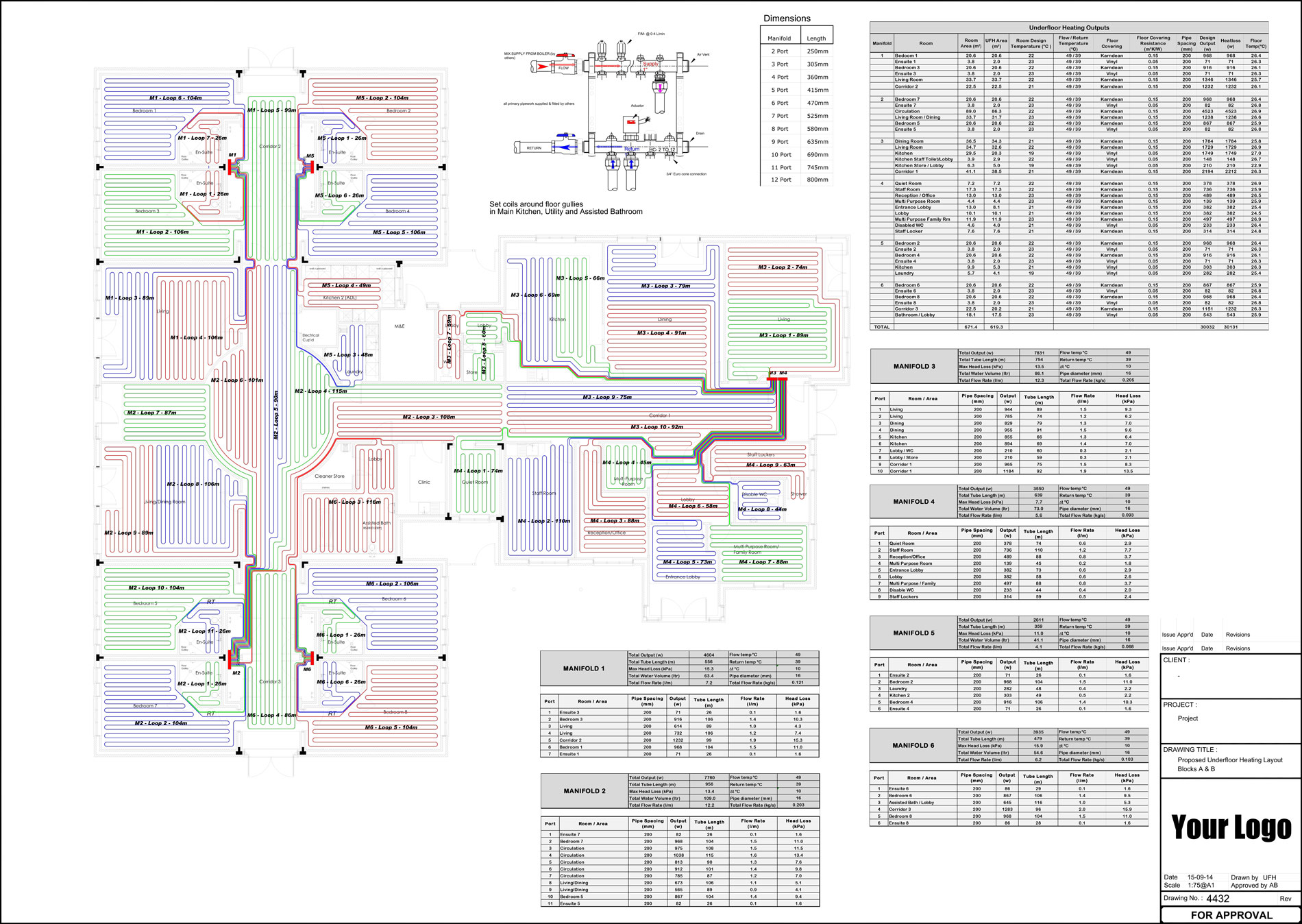
Once received, our in-house team produces:
- engineered pipe layout CAD drawings
- zoning and manifold planning
- heat output and performance calculations
- designs in accordance with BS EN1264 and CIBSE Standards
We do not use generic templates — every design is project-specific.
3. CAD Drawings Issued for Installation
Completed designs are supplied in an installer-friendly format, ready to be handed to:
- UFH System Suppliers
- UFH installers
- Screeding teams
- Contractors
- Client-facing documentation (if required)
4. White-Label Delivery (If Required)
All documentation can be supplied fully white-label, allowing trade clients to issue designs under their own branding.
Designed for Trade Professionals Only
Our process is built specifically for:
- UFH system Suppliers
Installers
Screeding contractors
- Developers and contractors